Throughout their career, quality inspection engineers for electronic components must work on various electronic devices using various technologies and applications. This article outlines the process an electronics engineer should use to inspect and certify a new product or system whose technology and application are unfamiliar to them. The methodology is laid out as a series of actions that anyone can perform.
The process used to test a new product or system is remarkably similar to the process people use while traveling to an unfamiliar city or town. Despite the widespread usage of Google Maps today, earlier generations relied on common sense and paper maps. They would locate several well-known landmarks through research or paper maps to help them navigate the city or town. Here, a similar strategy can be used using several steps and a leading methodology to delve deeply into the system.
How to Inspect the Quality of Electronic Components
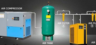
Low-power electronic inspection can be executed on a wide variety of electronic components, such as batteries, capacitors, diodes, inductors, fuses, relays, and others. Some of the inspections carried out to ensure quality include:
- Functionality Inspection
Any electronic system or product, regardless of how complicated it may be, is made to carry out a specified function or set of functions. Appreciating a product’s functionality is the first step in understanding it.
It could be a transmitter, for instance, whose function is to modulate information signals on UHF / VHF/microwave carriers. This product may be utilized in telemetry measurement systems, satellite communications, and other telecommunications applications.
- Specifications Inspection
The specifications of electronic components clearly state how well a thing must carry out its purpose. These also rely on the demands of the application. The quality test engineer must understand product requirements because it is their responsibility to ensure that the manufactured product complies with all necessary criteria.
For instance, a transmitter will include a frequency specification based on the application’s needs, modulation index, tolerance, performance requirements for harmonic and spurious signals, and so on.
- I/Os and Power Inspection
Every electronic device needs the power to carry out its specific functions. Either mains AC power or a DC power source could be used. For instance, a TV uses mains AC power, whereas a cellphone uses DC power. Therefore, the engineer must be aware of the product’s power requirements, including their values and current demands from the power supply, whether they are DC or AC.
Any electrical product will have various inputs and outputs for interfacing with other components or the environment (I/Os). The I/Os must be thoroughly understood. These I/Os may be radio frequency (RF), digital, analog, or power. Whether it is an output or an input signal, the engineer should be able to grasp it.
- Stress Levels of Application
Various stresses are applied to every product during use, storage, handling, and transportation. Stresses include hot and low temperatures, mechanical shock, vibration, thermal shock, humidity, and more. Solder joints, mechanical joints, and components may fail due to these stressors’ heat, mechanical, and chemical effects. The inspection engineer must therefore be familiar with all of these stresses and the corresponding product values.
- Functional Test Plan
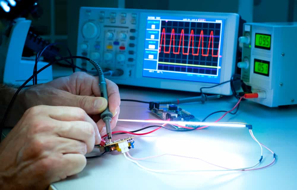
Typically, appropriate values inputs during application are applied to test products. By applying inputs over the entire range or according to the application, analog inputs can be inspected for their full dynamic range as per design.
Test RF/microwave receivers by applying an input signal with the proper frequency, level, and modulation. The proper modulation input must be used to test RF/microwave transmitters. The test plan should be carefully written to cover all I/Os and performance requirements.
DC voltage lines may be present in some outputs, which supply power to other subsystems. These should be noticed during inspection because they might fail after being integrated with other subsystems.
Every electronic product must function effectively across various supply voltage changes, likely to happen both during use and in the installation facility. The test plan must include test scenarios to ensure the product functions well over the allowable supply voltage range.
- Regulatory Requirements Testing
The electronic product should be inspected to ensure that it complies with EMC/EMI and other regulatory criteria after confirming via a functional test plan that it satisfies all I/O specifications, performance, and application requirements. To ensure that the device would function properly in the face of EMI from other electronic components and that this would not compromise performance owing to its electromagnetic emissions, EMC/EMI criteria are crucial.
- Stress Requirements Testing
As previously mentioned, the test strategy should include test cases to ensure the electronic product operates effectively. It complies with its specification and functionality requirements under known stressors during operation, storage, and handling.
In this case, exhaustive testing is not feasible. Critical parameters should always be identified and inspected for compliance before applying stresses for the requisite time, during the application, and after.
The operation should be guaranteed for transportation stresses before and after applying stress. Accredited environmental test laboratories and calibrated test equipment should be used.
- Testing before Delivery
Before the unit is delivered, an exhaustive inspection in accordance with the functional test plan must be conducted once the stress compliance tests are completed. This is because stress tests only cover the most important parameters, and any other slight failures under stress will only be discovered if exhaustive testing is done.
- Documentation
A test plan document must be created using all the data gathered in the preceding processes. Top-level diagrams of the device, displaying its power and I/Os, a description of its functionality and operation, supported by environmental stresses, a logical block diagram, performance, specifications of functionality, and regulatory and EMC/EMI requirements, should all be included in this document.
The compliance report should also include the following:
- The unit’s identification (model number, project number, serial number, etc.).
- The order of the tests performed.
- Any observations or problems with the tests.
- The unit’s clearance status for the specific applications.
Conclusion
The management and the customer will have confidence that the electronic component satisfies all requirements for the intended application thanks to inspections carried out in accordance with the document that is prepared and approved in accordance with information under section ten and test leaves filled in accordance with that document and the conformance report for the unit. The work of an electronic quality inspection engineer is completed at this point. EC Global Inspection is your sure plug for your electronic components’ quality control.